CaseLabs THW10
on Odin
- Motivation
- Ordering
- Unboxing
- Assembly
- Step 1: Chassis Divider, Bottom Chassis Section
- Step 2: Top Chassis Section
- Step 3: Front Chassis Section
- Step 4: Rear Chassis Section
- Step 5: Feet
- Step 6: Reservoir Mount?
- Step 7: Motherboard Tray, PCI Backplate, MB Handle
- Step 8: Switch Assembly and I/O Panel
- Step 9: Windowed Doors
- Step 10: Top Cover
- “Finished” Product
Motivation
As I mentioned in my welcome post, my prior case didn’t leave a lot of room for maneuvering. As such, I was not very consistent with upgrades or maintainence.
I am hoping with this new CaseLabs MAGNUM THW10 will help me with both of these.
Ordering
When deciding on this case, I had seen quite a few reviews saying that CaseLabs was top of the line; but also that they had very long lead times.
I had been planning on building a new system for awhile; but when my then current system died, it sped up my timeline. They had indicated on their site that there was a deadline to get orders in for the next batch of processing. I placed the order on May 5th and received it on July 28th.
As I did not have prior experience with CaseLabs builds, I knew that it was likely I would not be choosing the right accessory panels. I had not even chosen any of my other build components yet, so really didn’t know what I needed. I did a best guess with the assumption that I would likely have to order a few more accessory parts after building the case. Yes, I said building - they come flatpacked.
For the color, I chose gunmetal. I had wanted to do two-tone; but it was not an available option for the current deadline.
I also chose the Caster kit, a 140mm Bottom Accessory Mount, a couple PSU Support Mounts (was debating two smaller PSUs at the time) and a few Flex-Bay 5.25” Device Mounts. I went with the clear XXL windows on both sides and chose two 140.4 radiator mounts.
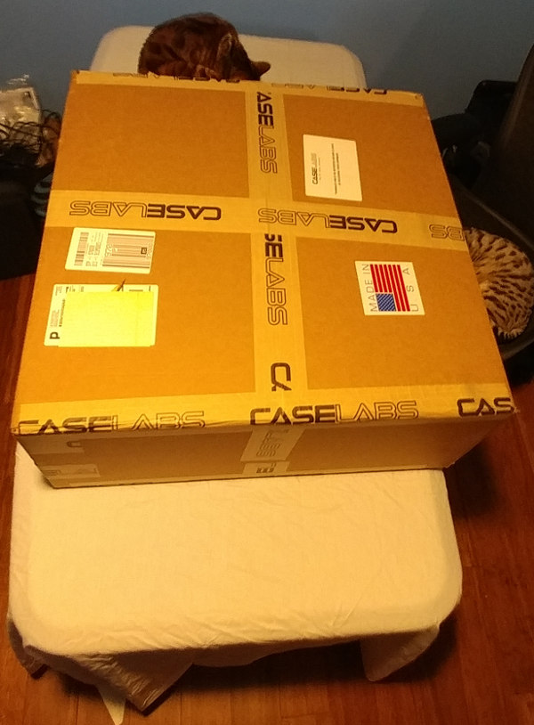
Unboxing
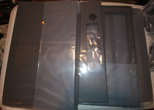
The shape and weight of the box reflect it being flatpacked.
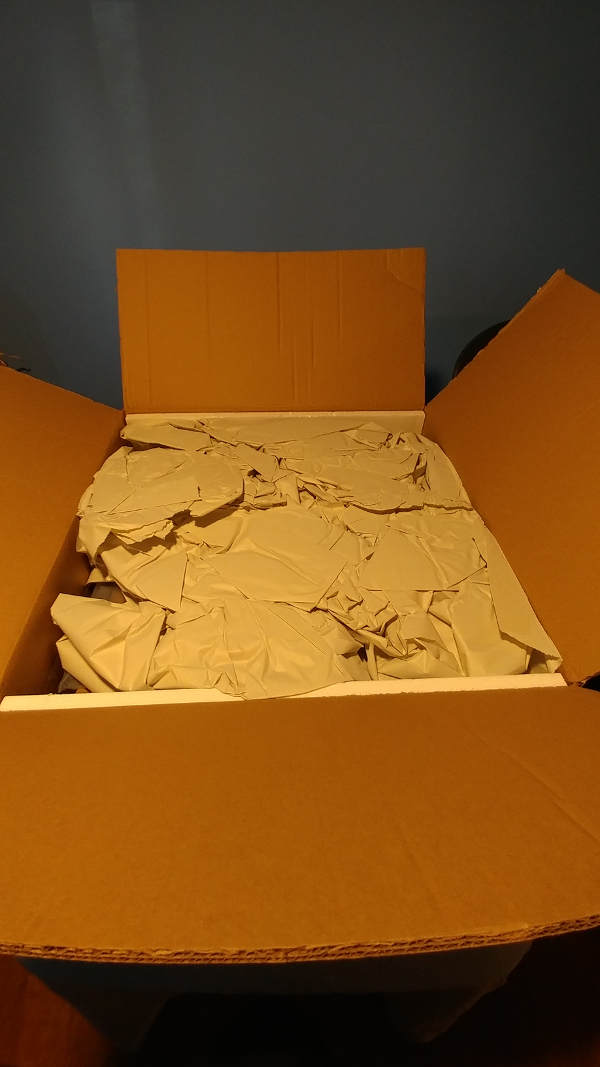
It was packed nice and tight, preventing anything from slipping around.
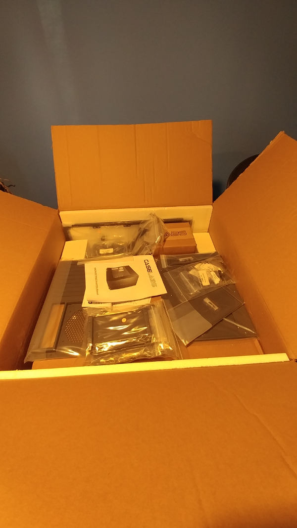
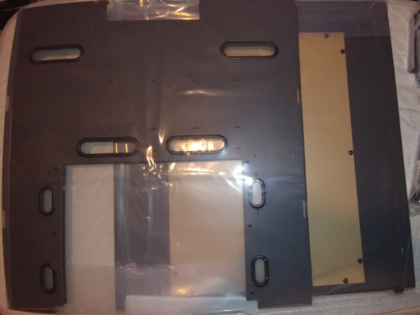
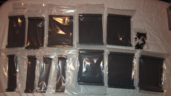
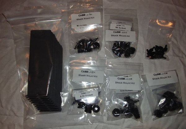
Under the packing material, everything was individually wrapped.
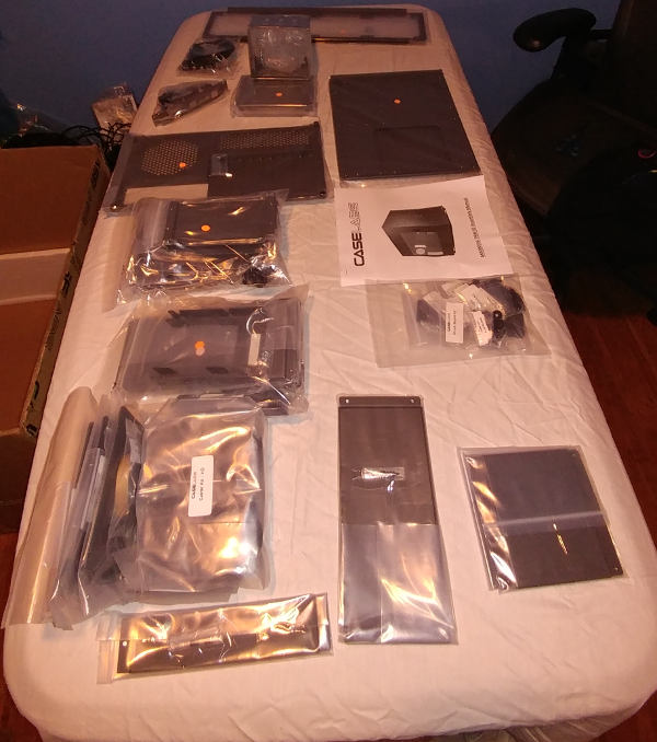
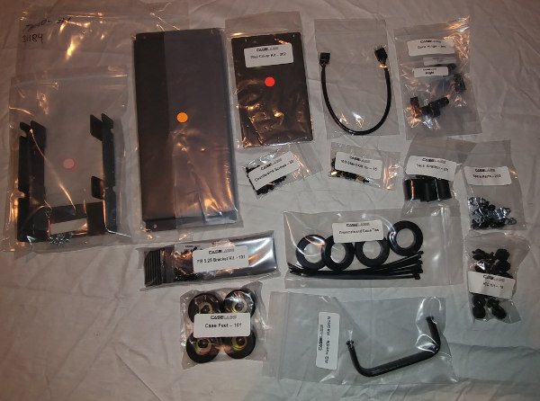
Pay attention to the countersunk screws in the center of the following photo.
Those are needed for the majority of the build.
Assembly
When I purchased the case, everyone said that it shipped with the manual for the TH10A. I’m glad to see that they included a THW10-specific manual. I’ll try to call out things I noticed weren’t quite right in the manual.
Before starting assembly, grab a phillips screwdriver and the countersunk screws mentioned above. If you purchased the XXL Window, you will also need a socket. 5/16” worked for me.
Step 1: Chassis Divider, Bottom Chassis Section
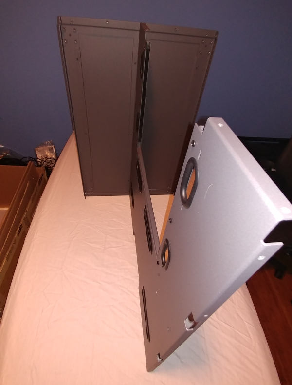
In Step 1, you are connecting the Chassis Divider and the Bottom Chassis Section. They mention to make sure to orient the front of the Bottom Section - but after reading Step 2, you start to second guess whether you did it correctly. Part of the confusion comes from dual use of the word “Front” throughout the manual. Sometimes it appears to be “Outside” (vs Inside) and sometimes it means “User-Facing Side” of the case (where the drives are as opposed to where the power supply is). In this particular step, I came to the conclusion they just meant Outside because I could not find any difference flipping it the other way. That’ll make more sense in Step 2.
Step 2: Top Chassis Section
In Step 2, the documentation for installing the Top Chassis Section is a bit confusing.
It mentions “Again, notice the two sets..” - but we didn’t have two sets of anything in Step 1. You do see two sets of holes, but it makes you question if you missed something in Step 1. From what I can tell, you didn’t - it’s a documentation bug.
It also points out that one end is further from the edge than the other. Hold something up to make sure, if you need to. In this case, the “front” means the “User-Facing Side” that we talked about before.
Really, their pictures are invaluable for making sure you are doing everything correctly - but some slight clarifications could reduce how long you second guess yourself.
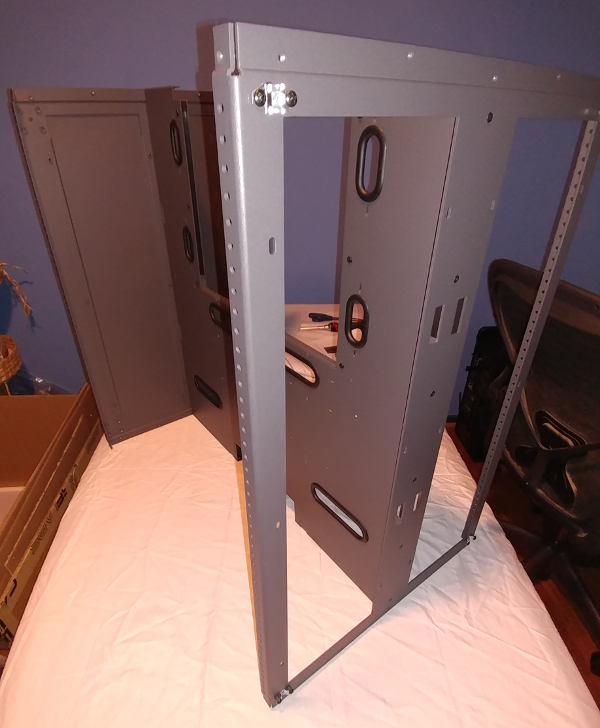
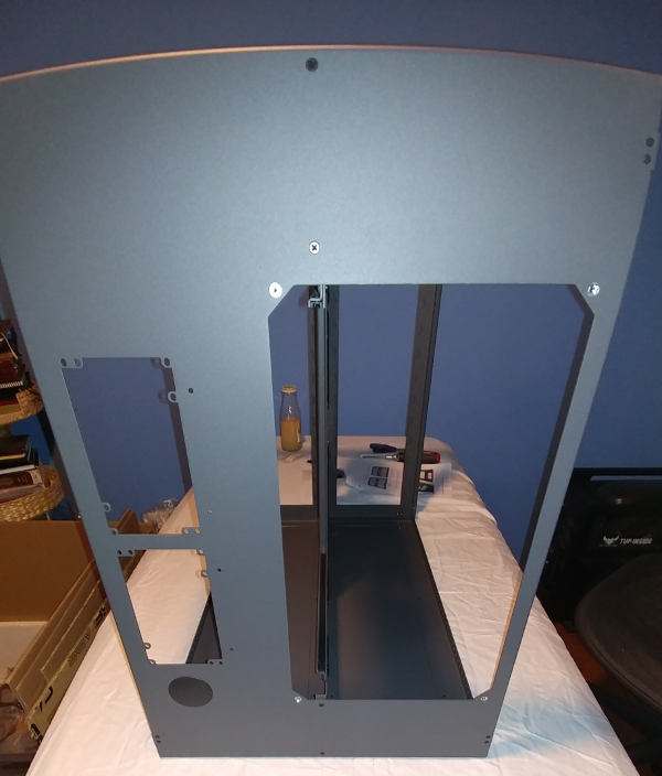
Step 3: Front Chassis Section
When installing the Front Chassis Section, the instructions mention “gently lifting up on each corner”. It’s not you - I had to use quite a bit of force to get them separated. I can only assume they will loosen a little over time.
When they mention that the switches are at the top, they mean put the circles at the top and the rectangle at the bottom. This could have easily been simplified by showing the panels in portrait instead of landscape mode in the manual.
In my photo here, I have re-installed the front cover. Later in the build, I realized I was not supposed to reinstall that part yet. Just install the Front Chassis Section without the cover for now.
Step 4: Rear Chassis Section
For Step 4, they are using the “User-Facing” version of Front. This is actually why I put the cover on in Step 3 - I wanted a smooth surface on my desk rather than risk bending or messing up the prongs/brackets.
When installing the Rear Chassis, I ended up stripping one of the screws. There are screws on the ends, and one on the side of each corner. I had started with the corner screws, but I think it would have been better to do the others first to pull the case together. Also when looking at the ends of the case, you will see two rows of holes, you are only putting screws in the bottom set.
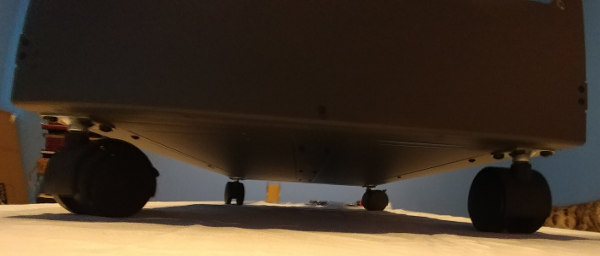
Step 5: Feet
Since I bought the Caster Kit, I chose to install those instead of the rubber feet.
All four casters have locks on them, which is nice. The case was already pre-drilled so that each caster is secured using 4 screws. It was pretty straightforward.
With all the casters locked, it still moves around fairly easily, but that may change once it’s fully loaded.
Step 6: Reservoir Mount?
The manual stated that the case shipped with the reservoir mount pre-installed on the wrong side, and that I needed to uninstall/reinstall it on the correct side.
Actually, it wasn’t pre-installed.
I had considered installing it into the case at this time, but I have decided to hold off for now. I will most likely install that when I install the Monsoon Reservoir. I am thinking it might be easier to install the Monsoon mounts to the mounting plate, THEN install the mounting plate. Could be wrong. We’ll see.
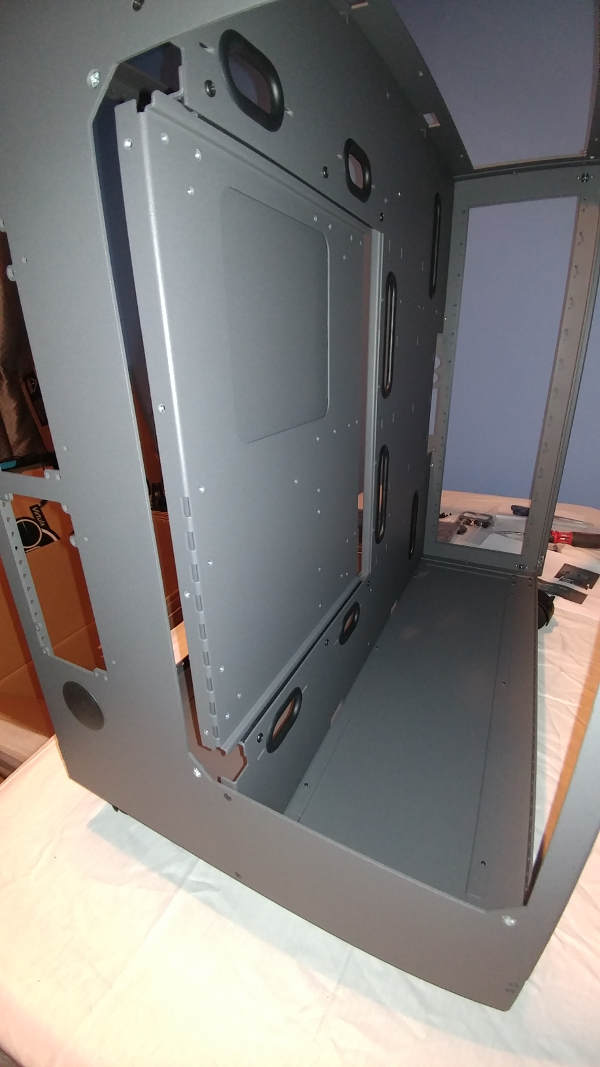
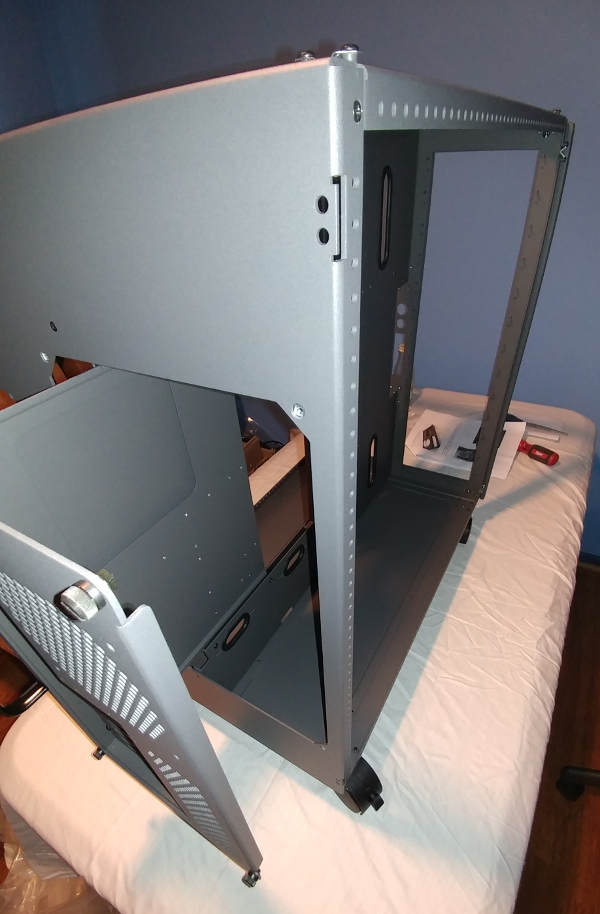
Step 7: Motherboard Tray, PCI Backplate, MB Handle
The design of the motherboard tray really intrigues me. It’s designed to alternatively be used as a test bench. Since I will be watercooling, I doubt I will be able to take advantage of that functionality much; however, down the road, if I decide to upgrade the motherboard or cpu, I can definitely see this functionality helping.
When installed, there is a handle to slide the tray in/out, and it just rests against the back of the case - it isn’t screwed into it. It looks like it SHOULD screw into it, and the manual does say “leaving slightly loose” which seems to indicate that it should… I may have to look at that again. Maybe they are expecting you to choose between test bench and desktop - in which case you may remove the nuts on the back and screw it into the case. I kind of like it this way.
I haven’t yet checked whether the test bench feet can be left installed while inserted into the case. Seems like that is something the manual should have mentioned. I’ll have to see how much clearance I have.
The picture in the manual is slightly different - the actual part has a fan cover grid instead of a raw hole.
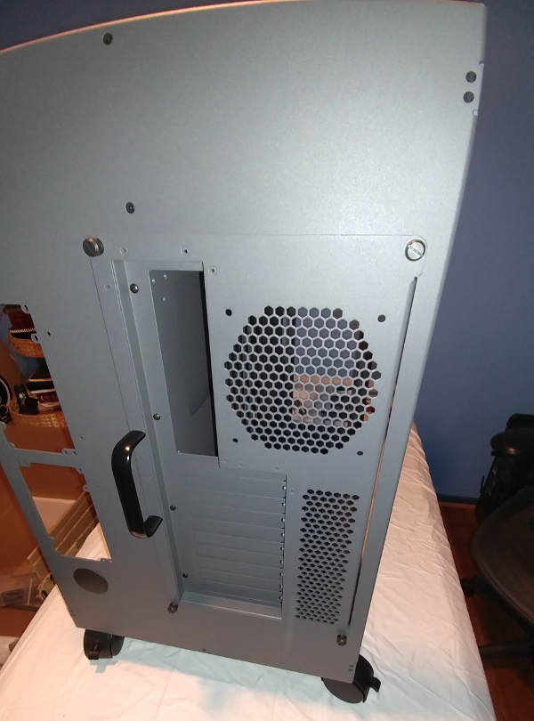
Here’s what it looks like when slid open.
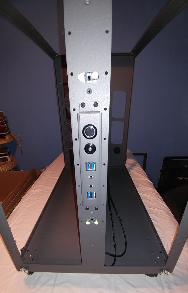
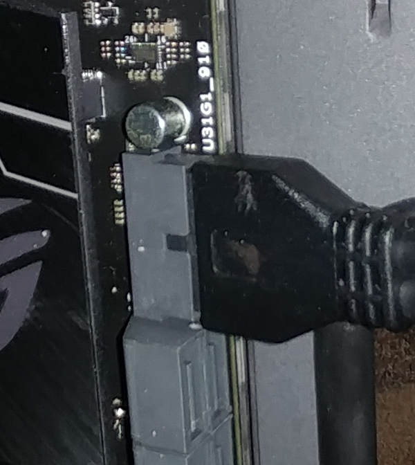
Step 8: Switch Assembly and I/O Panel
This step involves placing the I/O panel (USB/audio) inside the case, then the switch panel (power/reset) over them from the outside, then a separate plate on the inside to cover the wiring. The plate is not labeled, so you will need to dig through the bags to find the one with the right dimensions.
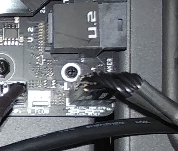
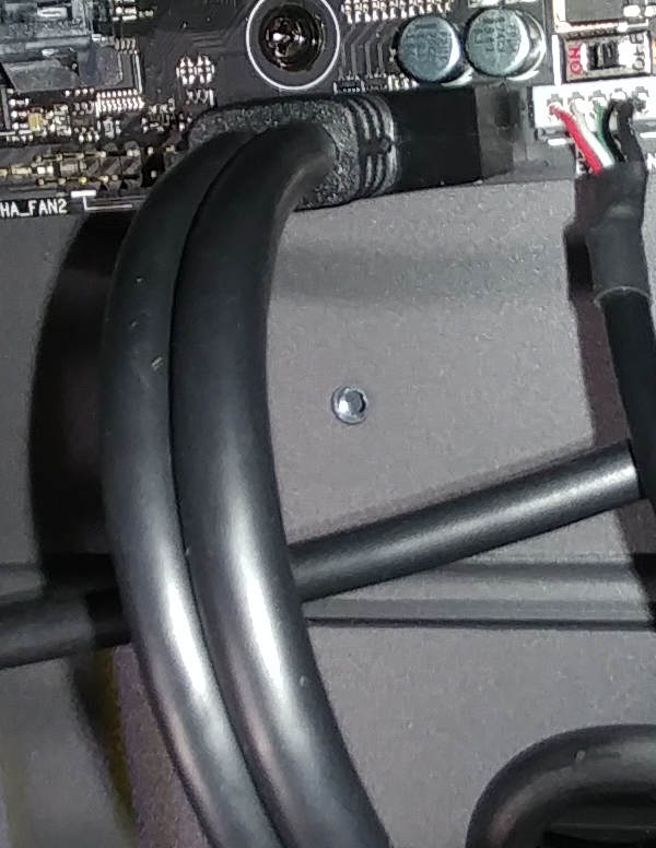
Connect to the Motherboard
This eventually connects to the motherboard.
The Power/Reset/HD LEDs…
The Front Panel Audio…
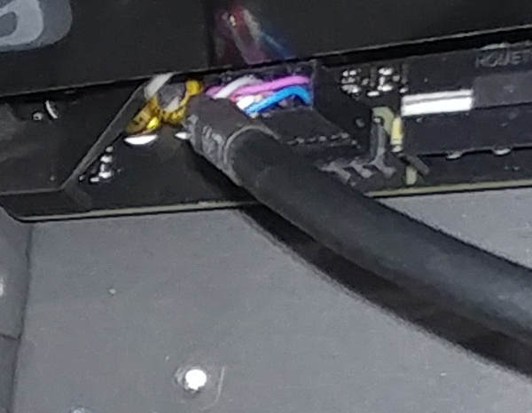
And the USB…
Step 9: Windowed Doors
The door hinges are in bags labeled Left and Right. It occurred to me during install that left/right are really dependent on which angle you are looking at the case. Really, the thing to keep in mind is that it is an L shape and that it should stick out of the case at the bottom of each hinge.
For the XXL Windowed Door, the window is pre-installed but has a film on both sides that has to be removed. You’ll need to use the socket wrench I mentioned above to remove all the nuts, remove the pane, spend a very long time removing the film from both sides, then put it back on and reattach the nuts. Probably should buff/polish it, but I’ll do that when I get done touching it ;)
Since I had two of these doors - it took a VERY long time.
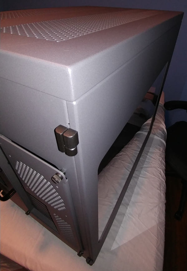
Step 10: Top Cover
The manual talks about locating and “extra bend” and shows a picture of a corner with one of the pins. If it isn’t clear, one end of the Top Cover has an “overhang” whereas the other side does not. The overhang will go above the “User-Facing” front panel.
This is also the step where they indicate that you should actually reinstall the cover in front of the Switch Assembly and I/O Panel.
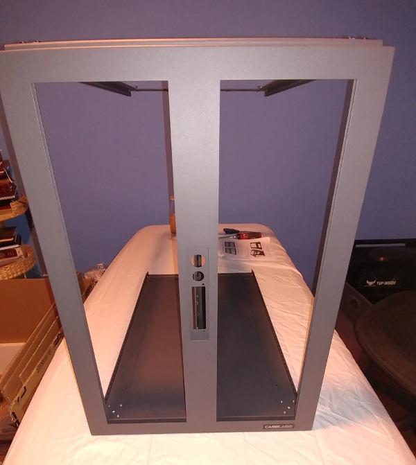
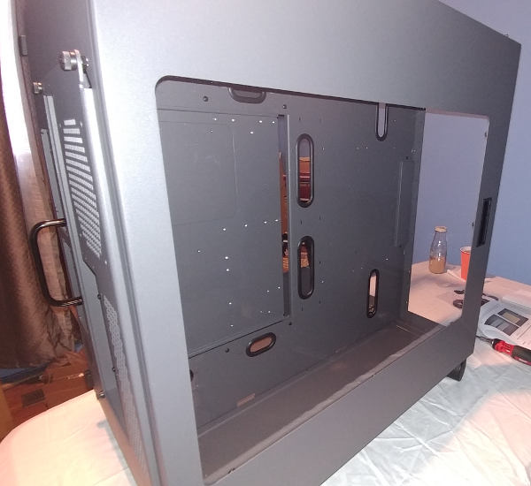
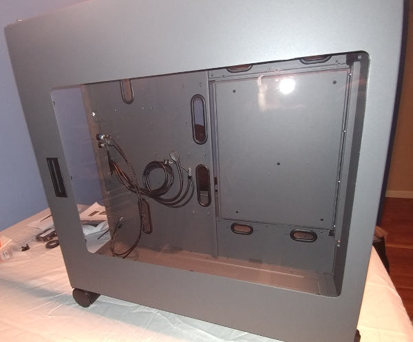
“Finished” Product
This image gives a good indication of size, in relation to my desk.
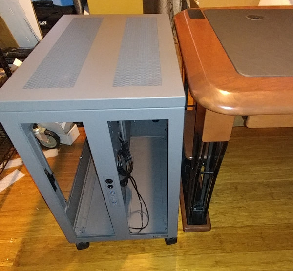
Obviously, there is nothing in the case. No drives, no bays, no filters, etc – so it isn’t really finished; but this is the stopping point for now. We’ll address those other things individually.