Solder Fume Extractor, Part I
on Electronics
Motivation
Anyone that has done soldering before will remember the fumes getting in your face.
As my eyesight has gotten worse over the years, I find I also tend to put my face closer to the work I am soldering. As such, it seems that the solder finds me much easier - even with a fan nearby.
The common solution is something called a Solder Fume Extractor… it’s basically a fan pulling fumes away from your work, often with some kind of filter.
In my particular case, I am also working to pack the majority of my electronic tools in a Pelican 1650 when not in use. As such, I need a solution that doesn’t take up too much space in the case. I also want to make sure that my power options for it are a bit versatile, given that this is really a portable electronics lab.
Parts
Fan
For the fan, I chose the Noctua NF-A14 industrialPPC-3000 PWM.
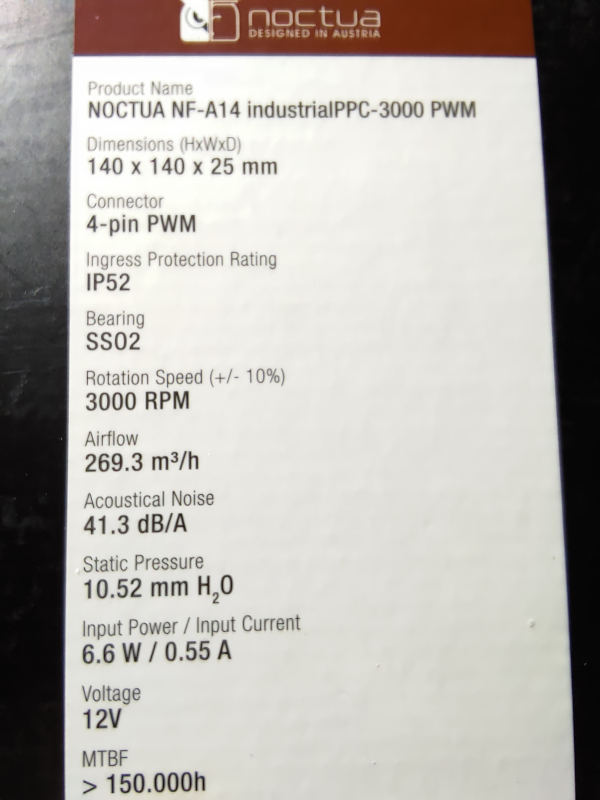
I chose this fan because it had a higher static pressure than most of the others while still being able to be driven by 12v. The higher static pressure is required when pulling through a filter. There are many other fans out there with higher airflow, but they require the airflow to be unobstructed. The main difference between the high airflow and high static pressure fans is the shape and spacing of the blades.
Fan Controller
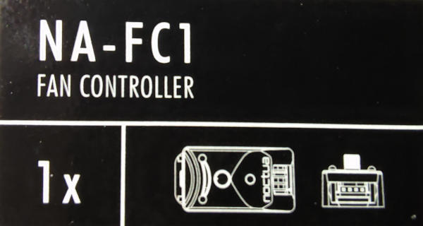
For the fan controller, I chose the Noctua NA-FC1.
Since this won’t be driven by a computer, we do not have a PWM signal coming in. Instead, the input is driven to 100%. This little controller allows us to dial the speed up/down by converting that to a proper PWM signal.
USC-PD Trigger
I had originally planned on using a standard DC power adapter/brick; but even when power strips are available they are usually annoying to get to and even more annoying to plug those larger plugs into.
To give myself some flexibility, I decided to make a USB-C PD input option. To do that, I will be using a ZY12PDN USB-C PD Trigger.
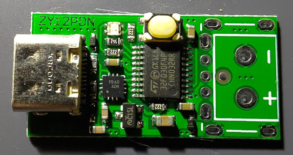
This little device will do the USB-C PD negotiation for you and is configurable.
The following chart was provided by the very useful YouTube tutorial by Kenneth Finnegan.
USB-C PD allows you to negotiate 5V, 9V, 12V, 15V, or 20V over the standard USB-C connector. The colors used on the ZY12PDN board for these are:
- Red: 5V
- Yellow: 9V
- Green: 12V
- Teal: 15V
- Blue: 20V
- Purple: Highest voltage possible
- White: Cycle through all the possible voltages changing every few seconds.
In our case, the NF-A14 fan is 12v, so we will force the device into a 12v mode.
I could have bought a trigger module that was hardwired to 12V; but this allows me to use the same adapter on other 5V fans (etc).
Sacrificial USB Extension Cable
I considered doing some cable modding and making my own USB cable.
In the end, it was just cheaper for be to buy a multipack of USB extension cables on Amazon and cut one end off.
Tools Used
I haven’t had an electronics kit since high school, so I have decided to start building one out. My last one was in a small metal toolbox. My new one is going to end up being in a Pelican 1650. I know, I know - that’s probably way too big… we’ll see ;)
Soldering mat
For the soldering mat, I used the HPFix mat. I didn’t make any attempts to put it through it’s paces, but it worked well enough. While cutting the sheath around the wiring, the pieces were pretty insistent about sticking to the mat. A slightly damp paper towel worked well enough to clean them up. Still, you’ll notice the mat doesn’t look very pristine in the photos… I’ll need to find a bettery way to clean it.
USB Adapter
I want options for power, so I wanted to also be able to plug it into the wall. For that, I used the Aukey branded USB-C PD charger. It’s 100w. My fan is 6w… however, if I am going to buy USB-C PD cables and adapters, I might as well buy ones I can re-use for multiple things.
Solder
I’ve never used lead-free solder before. This time, I went with the Kester 24-768-7603.
- Alloy: Sn96.5/Ag3.0/Cu0.5
- Core Size: 58
- Diameter: 0.020”
- Flux Type: No-Clean
- Lead-Free: Yes
Heatshrink
For the heatshrink, I chose Wirefy 3:1 dual wall adhesive-lined tubes.
Unfortunately, I couldn’t find any of my lighters and ended up using a match. Definitely not as elegant.
Brass Sponge
For the brass sponge to clean the soldering tip, I used one with a Weller silicone holder.
USB-C PD Power Cable
While a bit more expensive, I had chosen the Kevlar cable from NOMAD Goods. Could I have gotten a cheaper one? Of course! I just thought this one might be able to better hold up to the rigors of my electronics case and whatever projects I might end up using it for.
The one thing I do not like about their cables is that their USB-C cables only carry data at USB2 speeds. For the price, I would prefer them to be USB3 so that I could also have better transfer speeds for Android development, etc. That being said, I am buying this cable for power delivery not data.
Soldering Iron
My old soldering iron and soldering gun were both dinosaurs. I decided to try something new. I was going to go with the Miniware TS-80P, but instead I went with the Pine64 Pinecil.
I had bought it with both sets of tips. In this case, I used the DS-24 wedge tip.
Power Supply
I had originally bought the Pine64 PinePower to power the Pinecil; but I also used it for testing the fan setup.
In a real world setup, I wouldn’t be able to power both the Pinecil and this fan setup from the same PD port. More on that later.
Wire cutters and strippers
To cut the old wire, and strip it I decided to go with the Alphacool Eistools crimping kit. I had originally bought it with the intention of cable modding my Odin build.
USB Battery
I also tried to power the setup via the ECOFlow River Bank. More on that later.
Build
Now that we have our parts gathered, let’s do the build!
Prepare the Wire
First up, we need to prepare the wire. Take one of the USB extension cables. We’re going to keep the male end and cut off the female end. If you are unsure which to keep, it’s always best to try to plug the cable into the top of the NA-FC1 fan controller and see which end is left over.
At first I cut it really close to the connector. That was pointless, as it was very difficult to get their old heatshrink off. Instead, cut it off above the heatshrink. Note that, at least with this cable, the outer cover is very flexible but the end wants to fray once you cut it.
Next, we’ll trim the two wires that we won’t be using - just to keep them out of the way. In this case, we are keeping the red and black wire; but you should always check your cables in case the ones you bought are not following the same color arrangement. For example, this Noctua page shows yellow and black as the colors to keep. Figure out which end is ground (usually black) and keep both it and the one next to it. For our use case, you won’t need the RPM or PWM signal wires.
For my wires, I couldn’t easily remove the unnecessary wires since I would have to also remove the heatshrink from the other end. I decided to just trim them short. That may not be the case for your wires.
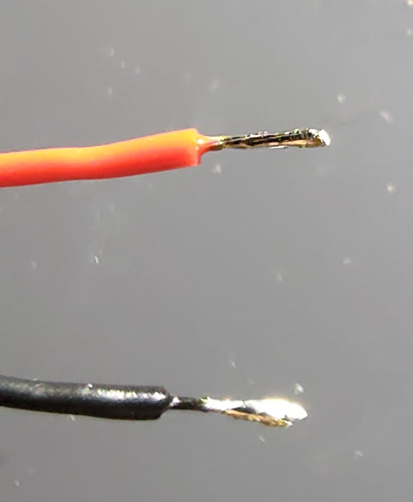
Next, you will want to strip the end of the two remaining wires (red/black or whatever you have). Since you cut off two others, you can use the removed pieces to gauge the depth of the cut you need. You want enough exposed wire to cover the terminals on the trigger board without it hanging over the edge.
Once stripped, tin the wire ends with some solder.
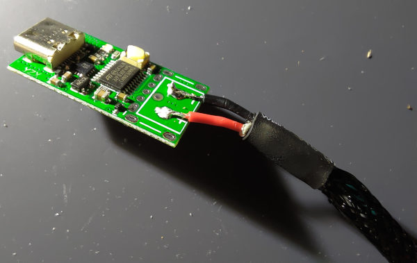
Attach the Wire
Before doing anything else, you will want to slip a piece of heatshrink over the wires (and that outer fraying covering). You can slide it down out of the way, but you will need it shortly.
Then, tin the positive and negative terminals on the trigger board.
Next, attach each of the wires to the board.
Slide the heatshrink down and warm it up. A heat gun or lighter should do the trick. I had to use matches because I couldn’t find my lighter and it was not ideal. I ended up melting the covering mesh a little.
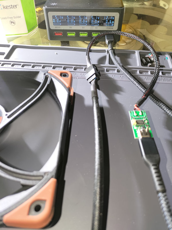
Initial Connection
For the first test, we will use the PinePower to drive it so that we have a visual readout of the power being drawn. For this test, we do not yet need the fan controller, however.
- Plug the fan into our newly modified wire.
- Plug the USB-C PD cable into the trigger module.
- Make sure that the fan isn’t going to fall over into anything (like your soldering iron) and plug the USB-C PD cable into the PinePower.
- Turn on the PinePower if it isn’t already
At this stage, the fan should not be running and the trigger module should have a red light for 5V.
Click the button once on the trigger module, putting it in 9V mode. This is enough to start the fan.
Click the button once again to put it in 12V mode.
Configuring the Trigger Module
Unplug the trigger module. You can unplug the fan at this point as well.
Hold down the button when plugging in the trigger module.
It will start flashing. Let go of the button; then cycle it from 5V to 9V to 12V.
(At this stage, I forgot if I long pressed the button again or not).
Unplug the trigger module.
When you plug it back in, it should negotiate directly to 12V.
If you have the fan lying directly on the table, you’ll notice it is drawing about 12v and 0.6 amps. If you pick it up, it will draw slightly less; maybe 0.4 to 0.5 amps. Once you attach the PWM fan controller, the speed of the fan will change the amperage, but it will remain at 12v.
Complete the testing.
- Test 1: PinePower -> USB -> Trigger Module -> Our new cable -> Fan Controller -> Fan
- Test 2: USB Wall Adapter -> USB -> Trigger Module -> Our new cable -> Fan Controller -> Fan
- Test 3: EcoFlow River -> USB -> Trigger Module -> Our new cable -> Fan Controller -> Fan
The first two tests will pass, but the 3rd will fail. Why?
The trigger module is forced into 12V mode. The EcoFlow River only supports 5v, 9v, 15v, 20v. When it attempts to negotiate 12v, EcoFlow denies 12v capabilities and it forces the unit to drop down to 5v. It would be nice if it tried re-negotiating 9v instead; but we did set it to 12v specifically.
If you want to run the fan in low power mode, you can switch the trigger module to 9v to run it from the battery.
Since our use case is to do solder fume extraction, I don’t want to run in low power mode, so will likely look for a different power bank to test it on.
What’s next?
- To complete the power options, I am also going to make a USB-C QC connector for it.
- I need to do a little work on my pelican case (diy trekpak system) so that I can determine how much clearance I have for the fan filter without crushing it. Once I have that, then I can proceed to determine what kind of case to make to house the filter, fan and electronics.
Those will need to be in another post.