Building a k3s cluster on Turing Pi 2
on kubernetes
Motivation
When I think about what my motivation is for building a k3s cluster on the Turing Pi 2, I feel like the question can be broken down a bit.
Turing Pi 2
Let’s start with why I chose to back the Turing Pi 2.
I backed their Kickstarter within 17 minutes of launch. Now, I admit that at one time I might have been considered a serial contributor (thus the Superbacker label), but I have mellowed down a bit over time.
I had been considering different ways of running compute nodes in my Sysracks 32U rack. Having multiple mounted on a single board, with a single power supply and network cable seemed like an efficient use of my outlets.
Originally, I had intended to mix-n-match different types of compute nodes on the board. Maybe some Jetson modules, etc.
Kubernetes
The next question is why I chose to run Kubernetes on the cluster.
There are various options you could do with a cluster. It could be dedicated entirely to Home Assistant for example. Or perhaps a homemade MMO. Or an MPI cluster.
I was planning on replacing Google Home (which has gotten worse over time) with Home Assistant; so that option might make sense. Running Home Assistant inside of Kubernetes comes with some restrictions w/ re to the add-ons.
I was already using Docker and Docker Compose. Having somewhere local I could deploy things would be nice. Local specifically, because I didn’t want to deploy to the cloud for some of the items (like my financial records).
Work uses Kubernetes. I never interact with it, but it would be good to expand my skillset. I tried running minik8s on my laptop, but feel like that was a bit of a mess. There are other options like Kind and minikube; but why tie up the local laptop?
K3S
So which version of Kubernetes to use?
This one was actually a fairly easy decision. The Turing Pi documentation had some guides for setting up k3s. Admittedly, they were geared towards running DietPi on the RaspberryPi, which I was not going to be doing - but it still gave me some guidance.
Timeline
| Date | Activity |
|---|---|
| 13 May 2022 | TuringPi sent me an email about the upcoming lanuch |
| 16 May 2022 | I backed the project on Kickstarter |
| 23 Dec 2022 | TuringPi.com account created, Original KS prices increased |
| 14 Apr 2023 | Delivery of Turing Pi 2 board w/o Compute Modules |
| 19 Jul 2023 | Charged for the 16GB Compute Modules |
| 26 Jul 2023 | Offered upgrade to 32GB, Charged for new price |
| 12 Feb 2024 | Delivery of RK1 Compute Modules and Heatsinks |
| 08 May 2024 | Ordered parts to start rackmounting |
| 20 May 2024 | Case assembled |
| 24 May 2024 | Rails attempted and rejected |
| 26 May 2024 | Cluster ready |
So as you can see, this process was just over 2 years in the making!
Specs
There are 4 RK1 modules.
| Type | Amount/RK1 | Total |
|---|---|---|
| Cores | 8 | 32 |
| TOPS | 6 | 24 |
| RAM | 32 GB | 128 GB |
| TDP | 7W | 28W |
| Storage | 1 TB | 4 TB |
Build Log
Sliger CX2137b
Choosing a chassis was not as trivial as I expected. If you are looking to do an ATX build, there are a lot of options. In my case, I needed a 2U Mini-ITX that would not shut down when idle power was low. This meant that the case and PSU options were intricately intertwined.
Jeff Geerling had used a MyElectronics case. I had seriously considered that for some time. They had a few options. The reason I chose to not go with their cases came down to the fact that I didn’t want to mount the NVME under the motherboard, and wanted them to be accessible. While they had cases designed with the Turing Pi 2 in mind, and one even had a hole for the PicoPSU - there was no room to mount anything extra.
The second issue I had was that a lot of the Mini-ITX cases did not have compatible rail kits that would work on the Sysracks cabinet.
The Sliger CX2137b is a 2U enclosure with optional rail kit that was long enough for my cabinet. More on this later.
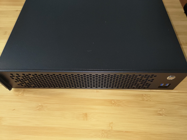
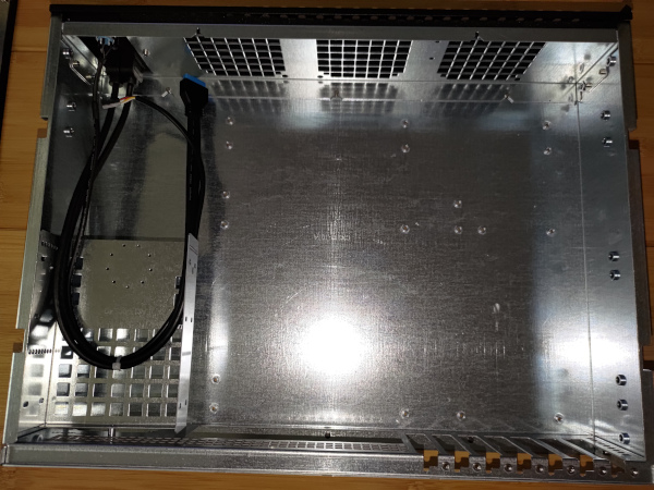
The cable that can be seen there contains:
- Front Power SW
- Front Power LED
- USB3
The IO Shield that came with the Turing Pi 2 fits the case; but more on that later.
Modify the case
Before I start mounting things into the case, I need to make some modifications to it. This is because the BMC SD card and the NVME for each node are all located on the bottom of the Turing Pi 2. While I understand that this was done to save space, and is not a big deal for small desktop plastic enclosures, it is not ideal for live modifications to a rack-mounted kubernetes cluster.
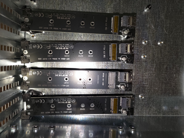
As such, I purchased an SD Card Extender and 4 NVME extenders.
The one downside to these boards is that provided NO mounting options at all. No screw holes, etc.
The solution I came up with was to use PCB feet on 3 of the 4 sides of each carrier board. I needed to then mount these to the case.
It didn’t turn out quite as clean as I would have liked, but it is at least working.
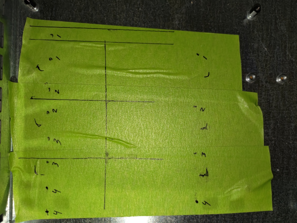
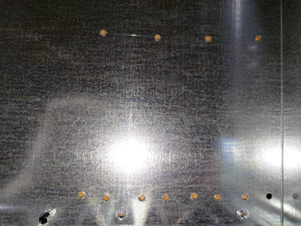
After drilling the holes, I made sure to install the PCI covers before installing the NVME.
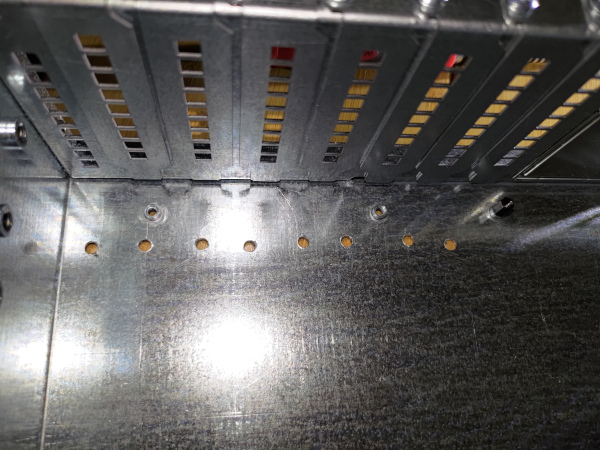
Then I was able to mount the NVME carrier boards.
You’re likely wondering why they aren’t straight.
Turns out I wasn’t careful enough when measuring and the drill slipped a little.
On top of that, the surface under the tape didn’t end up being flat. I have to console myself with not being able to see it once mounted.
Maybe someday I’ll replace the case and redo it by drilling from the other side instead.
I used M4 bolts that I had on hand for mounting the feet. I don’t like that they aren’t flush with the bottom of the case, so I’ll have to be careful not to mount another chassis directly under it for now.
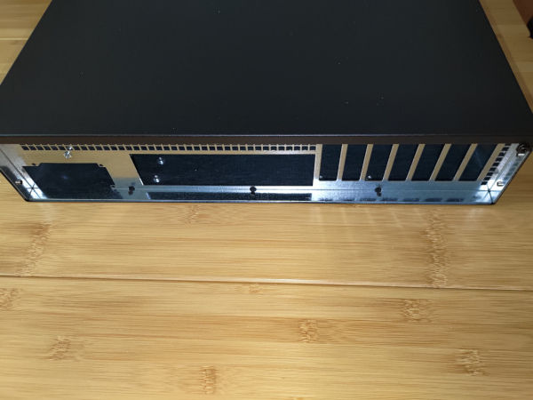
Rack Ears
I installed the rack ears next. Or at least, I should say I installed them for the first time.
Turns out that the provided screws suck for holding the ears on. They fell out and the ears fell off multiple times.
For reasons that will become obvious later, I eventually gave up on the provided screws and replaced them with my own M4x12 bolts.
I was going to install the rack rails next, but since they were greasy/oily I decided to do them later.
Noctua NF-A8 PWM
I used 3 of the Noctua NF-A8 PWM fans.
Airflow direction was printed on the fans. Make sure all your labels are facing the same way. Even though I was checking, I mounted one backwards and had to redo it.
There was the question of metal or rubber screws. It came with both.
I tried to use the rubber ones first, but was unable to get them through the hole in the case, so switched to the metal screws instead.
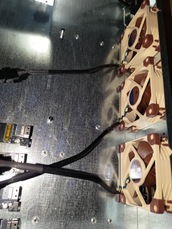
I am providing a PWM Controller that has two fan connectors, but using 3 fans. As such, I put a y-cable (included with the fans) on the two near the NVME.
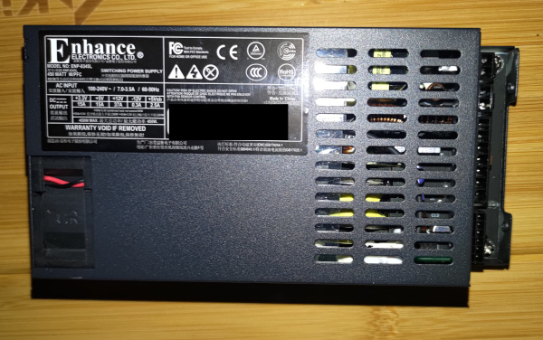
Enhance ENP-8345-L-OVT
I have been checking out the Overtek youtube channel where he does PSU teardowns. I bought the Enhance ENP-8345-L-OVT 450w FlexPSU from him. He did the Sunon fan mod on it. We had discussed the Noctua mod, but he said it would not work as well on low idle power.
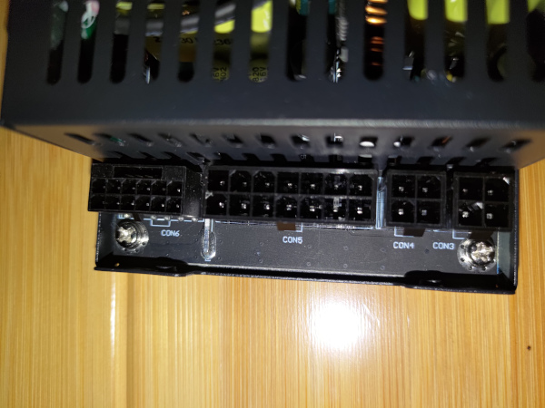
The loom set had multiple cables. I only attached the one needed for ATX Power, which I would later attach to the MB.
The PSU was a really tight fit under the drive cage. I had originally planned on mounting the PWM controller in that drive cage; but due to the fit and vent holes in the PSU, I removed the drive cage.
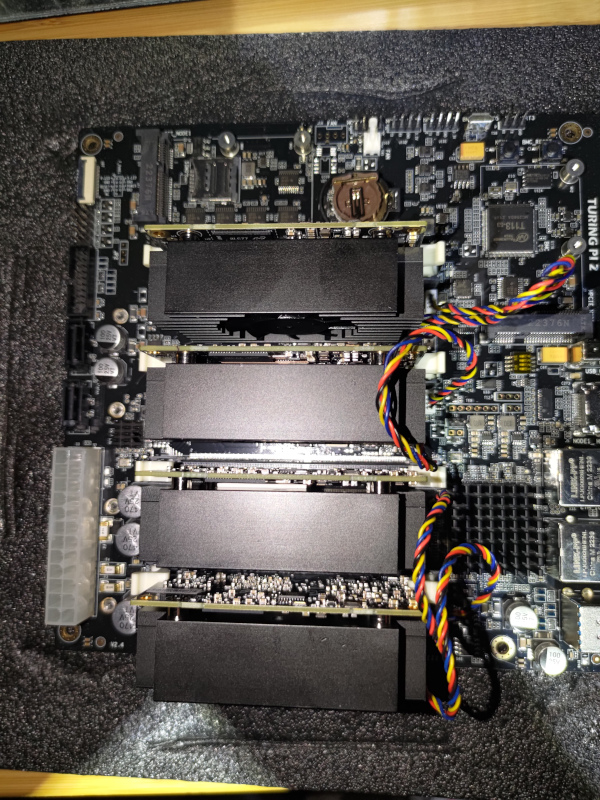
RK1
Next up was to prepare the Turing Pi 2 itself.
There is an HDMI Switch onboard. I just confirmed that all dip switches were set to OFF for use with the RK1 modules.
I installed the heatsink/fans onto the RK1 modules.
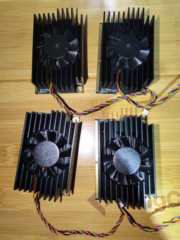
Then mounted the RK1 modules onto the Turing and attached their individual fan cables.
Extenders
As a reminder, both the BMC SD Card and the NVME for each node are inaccessible once mounted to the case.
As such, I am using extenders.
You can see how they attach here.
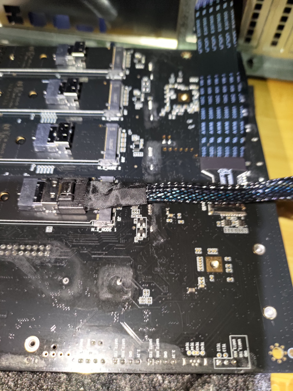
These NVME cables are much to bulky and raise the entire board up. As a result, I had to remove the IO Shield from the case and raise the entire Turing board up with spacers.
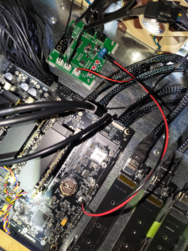
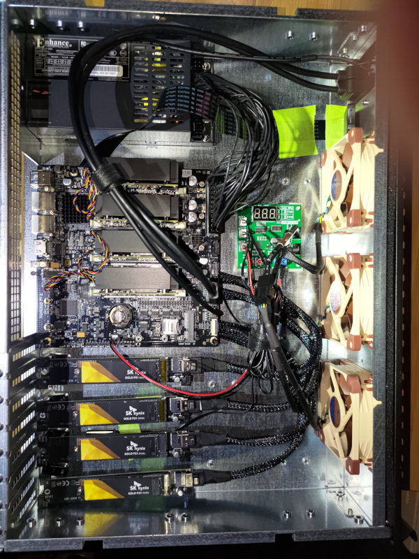
Final Internal Touches
I attached the PSU to the Turing MB.
I attached the case USB to the Node4-USB3 header.
I attached the front panel power switch and LED.
Then it was time for the PWM Controller. I needed to have some of these other cables in place to better determine where it would fit. I had put a thermistor under the middle of the Turing. It would control the one fan near the PSU and Turing MB. The other thermistor is in the middle of the NVME drives. It would control the fan near the NVME as well as the fan between the NVME and the Turing MB. I also attached their buzzer, which in hindsight was maybe not a good idea since I didn’t bother configuring the PWM controller. I really need to do that. For power, I used two leads from the Turing 12v Fan header to power the PWM controller. The PWM Controller itself is mounted with sticky standoffs.
The headers on the PWM Controller are:
- left side
- thermistor for Turing
- thermistor for NVME
- Buzzer
- right side
- PSU/Turing Fan
- Turing/NVME Fans
I attached the NVME drives to the carrier boards.
Taped the SD Card carrier to the case (temporarily).
Inserted the battery.
Some minor cable management.
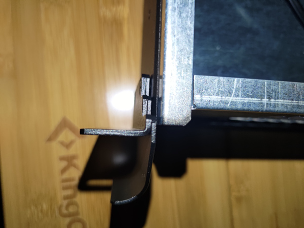
Rack Rails attempt
I got the 26" slides for 28" to 46" rack post spacing rack rail kit with the Sliger 2U chassis. As such, they did fit the case itself fairly well.
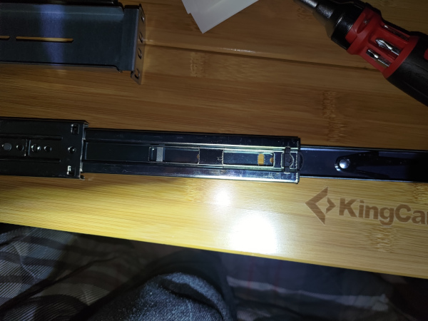
When I mounted them into my Sysracks cabinet, I was able to mount them to all 4 posts. They were not as easy as some Ready Rails, for example, but it was doable.
When I went to slide the chassis into the rails, it seemed to work at first. The problem was once the chassis reached where the ears would normally mount. It wasn’t wide enough. Just barely, but both sides hit. It needed a few more mm on both sides to fit. I spent a good hour trying to figure something out. The chassis or the rails fit, but not both.
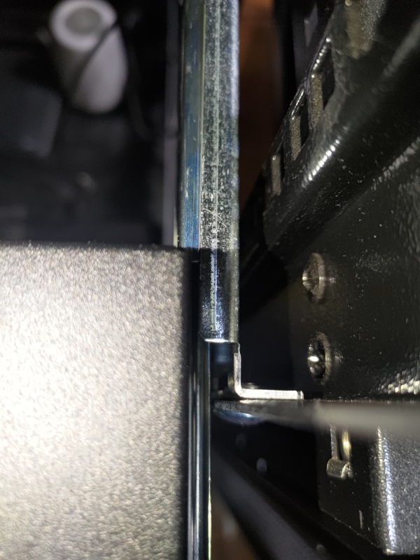
So what to do? I really want it on rails. How else am I going to tweak the PWM or swap out a node or NVME without downtime? However, that can be a tomorrow problem. For today, I just need it mounted.
I removed the rails from the cabinet and committed to mounting via the rack ears for today.
Given that the rack ears kept falling off, I was not about to mount them to the cabinet using them with the stock screws. I replaced them with M4x12 bolts and that worked pretty well.
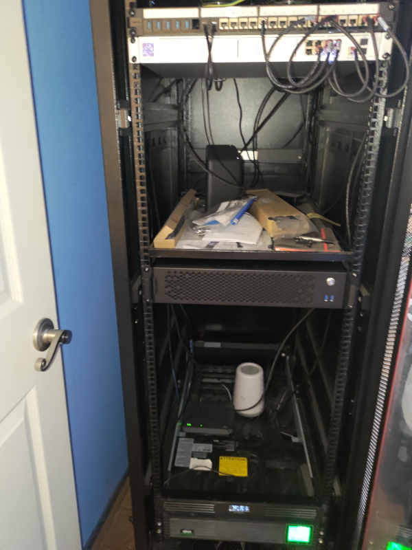
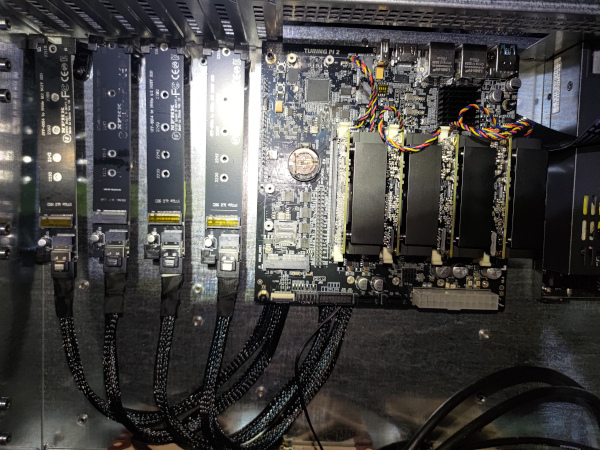
Connecting
I attached the network from Turing Pi 2 to the Patch Panel; then from the Patch Panel to the Unifi.
I attached the power from the Turing Pi 2 to an unswitched outlet on the battery backup. Hmmm, I’m going to have to change that. I guess it’s time to consolidate the two wifi routers so I can steal their outlet. Tomorrow-ish.
If anyone comes across this post, the correct power cable for the Enhance ENP-8345-L-OVT is NEMA 5-15P to IEC-320-C13.
I accidentally got the wrong one the first time.
BMC
It took a few tries to turn it on. It wasn’t clear to me what was going on, but here’s what I figure out.
- While the BMC is booting, the power button doesn’t really do anything.
- BMC can take 15-30 seconds to boot.
- If the power doesn’t come on by itself, you need to hold the power button down for a few seconds for it to boot the nodes.
- Turning off the power does not power off the BMC. You either need to press the BMC Reset (hard without the rails) or pull the power.
Accessing the BMC
First I tried accessing it via https://turingpi.local/ and then https://turingpi/. I was not having much luck with either initially.
Checking the Unifi dashboard, I could see that turing.localdomain as well as the mac address of each node had an IP address on the local network. Grabbing the IP address for the BMC, I was able to open the web ui.
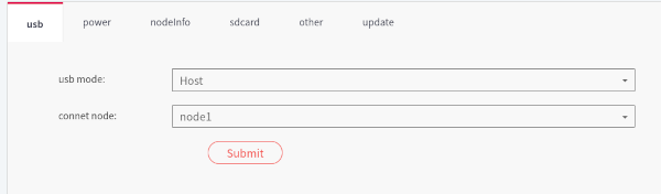
The UI did not look like the one in the documentation. It did not specify what version of the firmware it was either.
I tried upgrading the firmware via the web ui. It did not work.
I tried ssh to the BMC, but the credentials didn’t work. This seemed to indicate it was on the older firmware.
It seems that the board was shipped with the 1.x firmware. For some reason, I thought it had been shipped with the 2.x firmware. That also explains why the PWM fan header is not populated.
I actually spent a lot of time trying to troubleshoot this that I think I wouldn’t have, had the rack rails have worked. I pulled the chassis out of the cabinet while still attached to the network and power.
I tried to flash the BMC from the SD Card, but that didn’t work. The BMC never got into the flashing state.
I tried connecting the UART/TTL cable, but at first there was just no output. One Amazon review said that they had to swap pins. Worth a shot. I swapped the labeled TXD and RXD pins and got a line of text at power up. I pressed the BMC reset with these pins swapped and started getting output.
mount: mounting /dev/mmcblk0p1 on /mnt/sdcard/ failed: No such file or directory
Maybe the SD card was corrupted? I reflashed the SD Card, but it did no good.
Using the serial console, I enabled SSH. I tried copying the SDCard contents manually to mmcblk0.
Turns out, Amazon got me again. the SD Card extender cable was the problem. Removing that and plugging the SD card in directly allowed flashing. The unfortunate side effect of that is that I had to unmount the board to do it, and will again if I need access to the SD card. Not ideal.
Now https://turingpi/ worked.
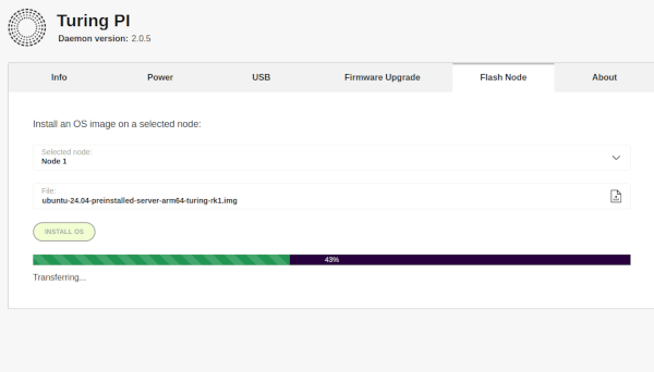
Flashing Nodes
I flashed Ubuntu Server 24.04 from this repo to all four nodes.
I noticed that the nodes no longer showed up in Unifi.
tpi
I installed tpi with cargo install tpi.
Running tpi info --host turingpi allowed me to see both the BMC firmware version and IP address.
The hostname later changed when I set a fixed name and IP in Unifi.
Based on these instructions, I was able to use tpi to access the serial console of each node.
Interjection from the Future
Originally, the BMC and all nodes were on the same network as the rest of the house (well, technically, the rest of the wired network). I went in and created a VLAN for the Kubernetes cluster and assigned it to that port on Unifi. I even wiped out the cluster and recreated it. We’ll just pretend that I did that before booting up the BMC the first time.
Setting up the Nodes
First, we ssh into the BMC with ssh root@turingpi.
We then turn off the power to all nodes via the web ui. This is so we can monitor the boot up.
Node 1: /dev/ttyS2
Node 2: /dev/ttyS1
Node 3: /dev/ttyS4
Node 4: /dev/ttyS5
From inside the BMC SSH session, we can access Node 1 with picocom /dev/ttyS2 -b 115200
Now, power on node 1 from the web ui.
When it powers on, it will ask for the username/password. We’ll use the default ubuntu/ubuntu, then be required to set a new password.
This would be different if we had used the desktop ubuntu image.
Then it’s time to run the apt update/upgrade.
Since I am running Ubuntu Server, I did not enable the CPU Govenor. I may consider it later, if it is running too hot.
Then, we need to setup the NVME. We can see the drive with lsblk or sudo fdisk -l /dev/nvme0n1.
I modified /etc/hostname and called it turing-node1.
I then modified /etc/hosts and added entries for all 4 nodes.
I also went into Unifi and set them all as Fixed IP. I also set the dns name in Unifi.
The IPs aren’t in order, but they won’t change.
Last, reboot via the web ui while still connected to picocom.
I couldn’t get picocom to exit, so I closed my terminal to close it. Repeat for Nodes 2-4.
Software Install
Next, we need to install some software.
I created a git repo and cloned it into Node1. I plan on keeping charts/deployments/etc in there.
k3s
For the following commands, <NODE1> refers to the IP address of turing-node1 and <TOKEN> refers to an auto-generated token (I used Bitwarden to make it).
On Node 1:
curl -sfL https://get.k3s.io | sh -s - --write-kubeconfig-mode 644 --disable servicelb --token <TOKEN> --node-ip <NODE1> --disable-cloud-controller --disable local-storage
Then on Nodes 2-4:
curl -sfL https://get.k3s.io | K3S_URL=https://<NODE1>:6443 K3S_TOKEN=<TOKEN> sh -
Update labels on Node 1:
kubectl label nodes turing-node1 kubernetes.io/role=worker
kubectl label nodes turing-node2 kubernetes.io/role=worker
kubectl label nodes turing-node3 kubernetes.io/role=worker
kubectl label nodes turing-node4 kubernetes.io/role=worker

kubectl label nodes turing-node1 node-type=worker
kubectl label nodes turing-node2 node-type=worker
kubectl label nodes turing-node3 node-type=worker
kubectl label nodes turing-node4 node-type=worker
Helm
Create a kubernetes config:
export KUBECONFIG=~/.kube/config
mkdir ~/.kube 2> /dev/null
sudo k3s kubectl config view --raw > "$KUBECONFIG"
chmod 600 "$KUBECONFIG"
Append the output of echo "KUBECONFIG=$KUBECONFIG" to /etc/environment
Now we can install Helm. I actually stored this inside the git repo mentioned earlier.
mkdir helm
cd helm
curl -fsSL -o get_helm.sh https://raw.githubusercontent.com/helm/helm/main/scripts/get-helm-3
chmod 700 get_helm.sh
./get_helm.sh
helm version
MetalLB
helm repo add metallb https://metallb.github.io/metallb
helm search repo metallb
helm upgrade --install metallb metallb/metallb --create-namespace --namespace metallb-system --wait
Unifi gave us a range of IPs for our VLAN. I assigned the very first one as static for the BMC. As such, we will offset the start range for MetalLB by one.
For below, we will use <START> to reference one more than Unifi said the range started at, and <END> for the end of the range Unifi identified.
Create metallb/deployment.yaml inside our repo
apiVersion: metallb.io/v1beta1
kind: IPAddressPool
metadata:
  name: default-pool
  namespace: metallb-system
spec:
  addresses:
  - <START>-<END>
---
apiVersion: metallb.io/v1beta1
kind: L2Advertisement
metadata:
  name: default
  namespace: metallb-system
spec:
  ipAddressPools:
  - default-pool
Now, we apply it.
kubectl apply -f deployment.yaml
Now, we’ll verify that traefik is taking the first IP in our range (<START>):
kubectl describe svc traefik --namespace kube-system
And we can verify that http://<START> shows the generic 404 not found
Longhorn
First we need to setup the NVME drives. For each node:
sudo apt -y install nfs-common open-iscsi util-linux
sudo mkdir /storage
sudo mkfs.ext4 /dev/nvme0n1
sudo su - root
echo "/dev/nvme0n1 /storage ext4 defaults 0 0" | tee -a /etc/fstab
exit
sudo systemctl daemon-reload
sudo mount -a
For this section, we will use <START+1> to define the IP address 1 higher than the start of the MetalLB/Traffic <START>
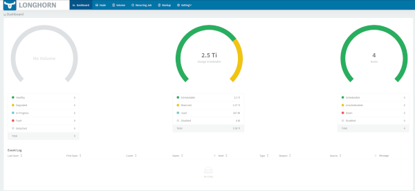
Now, on Node 1 we will install Longhorn to <START+1>.
helm repo add longhorn https://charts.longhorn.io
helm install longhorn longhorn/longhorn --namespace longhorn-system --create-namespace --set defaultSettings.defaultDataPath="/storage" --set service.ui.loadBalancerIP="<START+1>" --set service.ui.type="LoadBalancer"
Wait for everything to be running:
kubectl -n longhorn-system get pod
Verify StorageClass is present
kubectl get storageclass
- Open http://
<START+1>and Longhorn UI should be accessible.
This should show that it is indeed on <START+1>:
kubectl describe svc --namespace longhorn-system longhorn-frontend
Test Longhorn
Create longhorn/pvc_test.yaml in our repo
---
apiVersion: v1
kind: PersistentVolumeClaim
metadata:
  name: test-pvc
  namespace: default
spec:
  accessModes:
    - ReadWriteOnce
  storageClassName: longhorn
  resources:
    requests:
      storage: 10Mi
Apply it:
kubectl apply -f pvc_test.yaml
Verify that it worked:
kubectl get pvc
Note that it also shows up in the Longhorn UI.
Cleanup our test:
kubectl delete -f pvc_test.yaml
ArgoCD
On node 1:
kubectl create namespace argocd
kubectl apply -n argocd -f https://raw.githubusercontent.com/argoproj/argo-cd/stable/manifests/install.yaml
Next, we will wait for it to complete
kubectl get pods -n argocd
For this next section, we will use <START+2> to refer to the IP address 2 above the MetalLB <START>
We are going to give <START+2> to Argo.
kubectl patch service argocd-server -n argocd --patch '{ "spec": { "type": "LoadBalancer", "loadBalancerIP": "<START+2>" } }'
Login
Create argocd/get_credentials.sh in our repo.
#!/bin/bash

echo "http://<START+2>"
echo "Username=admin"
PASS=`kubectl -n argocd get secret argocd-initial-admin-secret -o jsonpath="{.data.password}" | base64 -d; echo`
echo "Password=$PASS"
Run the following to commit it and run the script:
chmod 744 get_credentials.sh
./get_credentials
- Open http://
<START+2>and enter the supplied credentials
Testing Argo
- Add the files from this repo into
traefik/error-pagesin your GitOps repo from before - Go into
Settings | Repositoriesand add our your repo from before- Use the SSH key you created on Node 1
- Go into
Applications | Create Application(orNew Appif it isn’t your first one)Application Name: error-pages Project Name: default Sync Policy: Manual Auto-Create Namespace: "check" Repository URL(GIT): <your gitops repo url> Revision: HEAD Path: traefik/error-pages Cluster URL: https://kubernetes.default.svc Namespace: error-pages
Find the traefik IP address:
kubectl describe svc traefik --namespace kube-system
- We can see it is at
<START> - Open http://
<START>and we can now shows a better 404 error page
Enable CLI from the GUI
kubectl patch role argocd-server -n argocd --type=json -p='[{"op": "add", "path": "/rules/-", "value": {"apiGroups": [""], "resources": ["pods/exec"], "verbs": ["create"]}}]'
kubectl patch configmap argocd-cm -n argocd -p '{"data": {"exec.enabled": "true"}}'
Next we will delete and restart the running pods
kubectl delete pods -n argocd --field-selector=status.phase=Running
Then wait for them to get into the Running state
kubectl get pod -n argocd
Conclusion
While this is just scratching the surface, I now have a 24x7 Kubernetes cluster running in its own VLAN that I can experiment and learn with.